Common wisdom dictates that the fuel tank should be level with the needle valve. With a tail dragger, this means the tank is lower than the carb with the model at rest. So, when the starter is applied, there is a wait for the churning engine to draw the fuel up from the tank. This can sometimes lead to a poor start. My first Camel had inverted Laser engine, with the carbs at the bottom of the model. The fuel tank was hidden behind the dash board, about eight inches head of fuel! The tube to the carbs started from the top of the tank, so that the fuel would not run to the carbs after filling the tank. when ready to start, a finger over the inlets and a few flicks bought the fuel down, then it was gravity fed and starting was very easy. The carbs were set so that when the TX trim was right down, it would cut off the fuel. The Laser twins were said to need two tanks, but I never did this. My single tank led to a Y junction then to the carbs. It ran perfectly well. In order to choke before starting, I had to cover both carbs at once. I now use one tank, but with two clunks and separate pipes to each carb. Now, each carb can be choked separately. A couple of choked cycles on each cylinder and the engine will start on the first flick. For fuel tanks, I mostly source these from the supermarket. Much cheaper, with a screwed top. Pipe fittings can be anywhere you want them. My 1/3 RF4 has a one litre baked bean square plastic bottle which is short enough to fit in the cowling. I can remove the tank on the field in 30 seconds if need arises. The head of fuel is six inches on this model.
Checking the CG position. We get asked this a lot. The CG on a model is not usually absolutely critical to the exact position I flew my Javelin with CG varying by FIVE INCHES. My Big Hurricane has recommended position - 5, 6, 7 inches. All the recommended CGs on our plans are as they were flown on my models.
A common misunderstanding, is that the CG should be set in flying condition - tank half full, gear retracted. In fact, the recommended CG can be with the model in any particular state. So, to make is easy, we say - tank empty, gear down. Set this way, your model will be the same as mine in flight. To illustrate the point ;- we could specify 'with the engine removed!'. This would work perfectly well provided the builder was using the same engine as me. But it would not be the easy way!
How do we check it? Usually with model standing on the ground or bench, tail wheel blocked up till the fuselage is level, Then lifting the model by the wing tips to find where it balances, No need to be too fussy over this.
Another way is to lift the model under the wing centre section, but difficult with a big heavy model.
Comparison of electric versus engine power.
|
|||||||
| Engine cooling. I often see quoted in magazines that the cooling outlet must be three times bigger than the inlet. What B...locks. Actually the same size outlet is OK. It will work because the air will simply exit at a higher speed than it entered. Look at the Spitfire cooling radiators. The inlet and outlet are about the same size, and the air is carefully ducted inside to reduce drag. The fact that the exit air travels faster means that it produces thrust, and I read that it added 5 mph to the aircraft's top speed! I have an inline twin engine in my model. People are always asking if the rear cylinder gets overheated. This assumes that the cooling air is entering the front of the cowling and exiting at the back, in a straight line. On my model the air enters in the scale air intake underneath, travels forwards, then sideways round both cylinders, then exits through the scale exhausts. When planning engine cooling inside a cowling, it should be borne in mind that the air may not travel the route you expect it to, so you may need to provide baffles or ducting to get the result you want. I have met several examples of mysterious engine cutting because of vapour lock. The engine stops dead, often when the throttle is closed, the fuel evaporates and the engine dies for lack of fuel. The cure is to move the fuel line to a cooler part of the cowl, or insulate it by wrapping or fitting air baffles. For a hot carb you will need cooling air ducted to the carb.
|
|
|
|||||||||||||||||||||||||||||||||||||||||||||||||||||||||||||||||||||||||||||||||||||||||||||||||||||||||||||||||||||||||||||||||||||||||||||||||||||||||||||||||||||||||||||||||||||
|
||||||||||||||||||||||||||||||||||||||||||||||||||||||||||||||||||||||||||||||||||||||||||||||||||||||||||||||||||||||||||||||||||||||||||||||||||||||||||||||||||||||||||||||||||||||
ENGINE TESTING without transmitter.
Have the throttle servo connector handily placed in the model,
connect a servo tester to control the throttle.
Telescopic vision.
Let me relate some stories.
1. Over thirty years ago I was learning to fly
RC with my Gangster 63. The flying field was quite big and had a
large tree outside the field, perhaps three hundred yards away. I
had seen models hit this tree a few times.
I was on landing approach, well inside the tree when I though 'No,
I'll be safe and keep high a bit longer'. So I flew high until I
was sure I was past the tree. Then I thought 'No, I will be
absolutely sure'. So I continued flying high until the model was
nearly at the strip, then I throttled back and dropped in to land.
Straight in to the top of that distant tree! I could not believe
it!
2. Two years ago I was landing the Hunter. I
had got in the habit of long approaches with the jets to give
more time to adjust the approach speed. I decide that a short
approach would be easier and so tried that.
The model came on finals at low throttle and full flap, but was
still off the end of the runway. It seemed to hover there without
moving forward in the quite strong wind. I chickened out,
expecting a tip stall [I was pleased to see that it did not] so I
opened the throttle, lifted the gear, and wondered where the flap
control was. I had to look down to find it and retracted the
flaps. The model was quite happily coming towards us but had
turned slightly off the runway and was just behind us.
As the model passed, we were able to hear that the engine was
still running [could not hear it downwind]. So I turned into
another landing circuit and throttled back.
This was meant to be a smaller circuit, but proved to exactly the same as the first one. Again I opened the throttle, lifted the gear, and this time the flaps straight away. The model was at about ten feet from the ground and a long distance away. The model again turned slightly off the runway and reached us a few yards behind where we were standing. I said to Jim 'Has the engine stopped' He agreed it had, so I thought No Problem, I'll land right here on the short grass. Two hundred yards away was the edge on the airfield with high security fence and massive prickly hedge. The model went behind the hedge. We both could not believe it! It looked like a full size Hunter in relation to the hedge. When we re-ran the video, again we got the same impression and had to run it several times until we could see that yes, it was a small model behind a large hedge.
3. This year I was flying my slow Bleriot on a calm day doing tight circuits and touch and goes. There was a small sapling 100 yards away and I was shocked to see the model pass behind it. Lucky not to have wrecked the model in the tree.
So it seems that when we fly RC models, our perception is distorted and we think the model is much closer than it is.
JET SPEED
I have flown all the jet models we produce and
I estimated that the top speed was about 100 MPH.
Then two different customers told me they had carried GPS units
in their Super Reapers to get a speed readout. The Super Reaper
with 14 lbs thrust MW54 was doing 200 MPH in level flight, no
retracts. I had to revise my thinking . I now think that all our
jets will do similar speed on a normal 8kg thrust engine.
I had noticed that when flying jets, sometimes my 180 degree turn
at the end would be very wide, with the model getting a long
distance away. This was unpredictable and made positioning
difficult.
I now think I understand. It is to do with the airspeed. At lower
speeds, the model would turn much like a prop driven model, but
at high speed the turns would be much bigger. A lot of elevator
would be needed to get round and this was unexpected. I read
somewhere that a full size Lightning would take twelve miles to
turn at full speed. This makes sense and explains one of the
difficulty with flying jets, you have to be more aware of the
speed differential which is available, and how this affects
handling.
JET THROTTLE
Another problem with flying jets is the lack of sound from the engine This is most apparent on the landing approach. I found that I would often approach with a much higher throttle setting than I thought I was using. I realised that when flying a prop driven model, I was judging the throttle opening not by the stick, but by the SOUND of the engine. This makes jet flying more difficult.
I Cut three notches in my Tx throttle quadrant
to give a feel at 1/4, 1/2, and 3/4 throttle positions. This was
not as effective as I had hoped.
I sometimes shut the throttle completely on the downwind pass to
find the position of the stick, then open again to 1/4 for the
approach.
Colour perception.
1. Colour perspective.
It is a common belief that scale models should not be painted in
the exact same colours as the full-size, but that the colour
intensity should be reduced. This is because of so called 'colour
perspective'.
If you look at a scene of distant hills, it will often be seen
that each row of hills appears in paler colour behind the hills
in front. This is undoubtedly true. I think this is due to mist
which has the effect of 'greying out' the image as it gets
further away. But the same view in bright sunlight does not have
the same effect. I have not as yet gathered any evidence for this.
However, when we are considering the colour of a scale model, we
are not looking at the model from miles away, not even 100 feet
away but just a few feet. In fact the most critical distance
would be the five metres from the centre of the model, as in
competition judging.
Consider this; The model is placed at 5 metres from the observer
and the full size aeroplane is placed at a distance where it
looks the same size as the model. So a 1/4 scale model would have
the full size four times 5 meters = 20 meters away.
A 1/3 scale model would be 15 meters, and so on.
I have heared it stated that if you hold a colour sample up, with
another sample some distance behind, the difference in colour
strength can be seen. I did not agree with this so I did an
experiment.
I took two green dustbins as my samples, on a bright sunny day and took digital photos of the two at various spacings relevant to model scales. The set-up is shown in the first photo.
The results are shown below.
I cut out small samples from each of the bins and overlaid the
more distant sample in a small panel over the large panel which
was the bin at 5 meters.
| You wil notice that in samples 1 to 5
there is virtually no difference in the colours. Samples 6 and 7 were taken with the furthest The white streaks are scratches on the
bins. I think this proves that for the
purposes of scale model |
 |
Further sections to be added
2. Paint.
3. Gloss.
Gloss and matt paint of the same colour look different. Gloss
will reflect the colours of the surrounding scene like a mirror.
(Look at the side of a shiny car. You will see the scenery which
is behind you, the skyline of trees and buildings, you own
reflection, etc.)
Matt partly does this, but also scatters the light much more and
this usually makes the matt colour look lighter.
4. Light.
The light from the sun varies with the time of day and weather
conditions. This alters the colours perceived by the eyes.
However, the brain compensates for this, so we can tell colours
without noticing the change, even when wearing sunglasses.
5. Shape.
6. Luminance.
We think of using bright colours to make a model easy to see in
the sky.
But why are bright colours easy to see? The reason is that they
are usually a contrast from the dull
background colours. But if you were in a sandy desert in bright
sunshine, a bright orange-yellow would
be the worst colour to stand out.
The sky is not the same as the ground, it has high luminance
compared to the ground in most conditions. Because of this the
best colours to contrast with the sky are DARK colours. A white
or yellow or orange model can become hard to see when its
luminance becomes the same as the sky behind it. A black model is
the easiest to see because it always contrasts with the sky.
Exceptions are when the model is below the horizon, when the
reverse applies, and at night when any colour is black!
7. Reference
8.Weathering
9. Reproduction.
10. Perception.
Incidence, thrust lines, trims on scale
models.
We get many enquiries about what incidence, side thrust etc
should be used on our scale models.
The wing and tail incidences are to scale. They were chosen my
the aircraft designer to suit the expected loads
and speeds of the aircraft. Our models are SCALE and so keep to
these as they should be. To change them would
make the model non scale and would not look right.
Trims. The trims on a full-size aircraft are for the pilot to
adjust so that the stick loads are reduced to suit
different speeds and loads. The trims would be changed often in
flight.
On an R/C model we would set them for level flight at a cruise
speed and normally not move them again.
Exceptions might be to set trims for lower speed on a flat calm
day, or for full throttle flight in a gale.
I find that most of my models fly with quite a lot of down trim.
This can be explained by the fact that the model is
much lighter by comparison with the full-size, and may be flying
at higher than scale speed.
I also use right rudder trim. I notice many photos of the full-size
Spit show it has a lot of down trim.
Free flight models use offset thrust lines to control the model
as the power changes through the flight.
With R/C we have controls to do that job.
If you trim the model to cruise at mid throttle, then going to
full power will make the model climb, but
that is probably what you wanted.
For competition aerobatics, offset thrust lines
will make the model easier to fly
to accurate patterns. This would also be effective on a scale
model, but would spoil the appearance.
Remember, the full-size version of your model would also react to
power changes and the pilot would have to
adjust the controls accordingly, so you must do the same with
your model.
So, build the model to the plans. Match the incidence as shown on
the plans.
No need to ask how many degrees it should be. I don't know and I
don't need to know.
Don't worry if your trims are not central - they don't need to be.
CG position. The plans show the CG position which was successful
on my model. If a range is shown,
it means my model was test flown over that range. On the Javelin
the range was five inches!
On tail draggers, a forward CG means nose-overs and heavy
unresponsive controls, a rearward CG means
sensitive controls and difficult tracking on the ground,
So it is a compromise. If you have a model which noses over AND
ground loops, you could say it has the perfect CG position!!
Flight attitude on a scale model.
I have heard it said by several well know
modelers ‘that model is flying tail down, it must need more
nose weight’ . This is quite wrong.
Aircraft attitude in level flight is determined by
airspeed. The slower the airspeed, the higher the nose will be.
The wing has to support the weight of the machine, and it needs
greater angle of attack to do this at lower speeds. The pilot has
to pull the stick back to maintain level flight.
The effect can easily be seen by flying at different
speeds and observing the attitude, but it is not so obvious to
the pilot inside the aircraft.
When an aircraft is landing, the attitude is nose up compared to
high speed flight, but the cg has not been moved!
CG position does affect the aircrafts attitude to a small degree,
but in the opposite sense to that mentioned in the first
sentence.
The most noticeable effect of CG position is on longitudinal
stability. A rearward CG makes the elevator more sensitive, to
the point of uncontrollability.
Many FF models use a rearward CG because it is more efficient.
This makes the tail provide some of the lift but makes the model
less stable. The wing now needs less lift and so the attitude is
slightly less nose-up.
If the CG is moved very far forward, the tail has to balance this
with a downwards force. The wing then needs extra lift to
compensate, and so the attitude has to be slightly nose high.
So when you see an aircraft flying ‘tail down’, it is
because it is flying slowly with stick held back.
To stop it, open the throttle and move the stick forward to keep
in level flight.
I think the mistaken view was developed by free-flight modelers,
because a FF model has no elevator or throttle controls.
Trim position.
I've heard this said. "My model
flies with down trim on the elevator, it should be level, so
there must be something wrong."
Trim is provided on models and full size so that the aircraft can
fly level "Hands off". The trim required depends on the
airspeed, so slow flight needs UP trim
and high speed needs down trim. There will be a speed where the
trim is central. All my models are set with some down trim
because I fly fast for smooth flight and
to help in strong winds. On the rare occasions of still air, I
can move the trim up and fly slowly.
It was pointed out to me that most photos of Spitfires in flight
show them using down trim, just like my models!
Frequently asked questions.
What engine do you
recommend? There are thousands of engines available. Most of them
are good. I have never set eyes on most of them and certainly
have no experience. The
size range we suggest are valid, best to stick to them. The only piston engines we now
use are Lasers.
What paint do you recommend?
I have tried many types and
have trouble with all of them! I am now returning to Epoxy paint with our own MrEpoxy.
I have now tried digital servos
and found that , although the power quoted was no more than a
normal servo, the HOLDING power was vastly better. Try moving a
control surface against the servo holding power. You can easily
back drive the servo. With a digital servo of the same torque, it
is almost impossible to move the surface. Now that digital servos are cheaper, I
will use more of them in future.
FLUTTER
My thoughts on control
surface flutter are as follows.
Turbulence is usually present around control surfaces, and
turbulence tends to be unstable. This means that the airflow
oscillates from one side to the other. Models can often be seen
to wobble slightly in flight and this is the result of this
oscillation.
Experiment; Take a stick of balsa and push a screwdriver through
the middle of the stick. Put a lump weight on one end of the
stick. Hold the screwdriver so that the stick is free to revolve.
With a gentle to and fro movement of the hand, the stick can be
made to swing like a pendulum. It is quite easy to get the stick
to spin round rapidly with very little hand movement. This is
similar to the wobble in air turbulence making a control surface
swing from side to side.
Now add another weight to the other end of the stick so that it
balances exactly. Now you find that no matter how hard you swing
your hand, you cannot make the stick swing at all. It needs the
pendulum effect for it to work.
So if you add balance weights to your control surfaces, ahead of
the hinge line it will no longer be possible for flutter to occur.
Of course you should still make a good job with your linkages and
hinges, but this will not now be critical.
Flying safety.
The most common cause of crashes is, as we
all know, pilot error. But some crashes are caused by mechanical
failures and improvements to our installations can improve
reliability.
It is common practice to use
a separate servo on each aileron, mainly because it is easier to
do than using one servo and long linkages. A bi-product of this
is better reliability. If one servo fails ,the remaining one will
give enough control to safely land the model. On most of my
models, I now do the same with the elevator control. Where the
elevator is split, it is quite simple to work each half with its
own servo. (Sopwiths, Javelin, Lightning. Spitfires etc.) I find
that the cheapest servos are normally powerful enough, with two
servos you have twice the power and much better reliability.
How much more reliable? Well, its not just twice as reliable, but
much, much better.
Suppose your servos fail once every 1000 flights. The chance of
both failing on the same flight are 1000 x 1000. Or once per
million flights. Mathematically it is - [reliability factor,
squared].
Batteries.
Some people try to improve reliability by using a separate battery
for the receiver and the servos. They do not realise that this is
in fact LESS reliable. As both batteries are needed to control
the model, then failure of EITHER battery will result in loss of
control. So, if the battery failure rate is once per 500 flights,
then in this case it will become twice in 500 flights, HALF as
reliable as one battery. The Multiplex 12 channel Rx. has a built
in facility to use three separate batteries, which would reduce
reliability to 1/3 that of a single battery!!!
There is a simple way to vastly improve this situation. Instead
of buying say, one 2000 mAh battery, buy two 1000 mAh.
batteries, but connect them in parallel. This is done by using
two standard switch harnesses, and plugging these into the
receiver. Not into a Y lead, since this means you are relying on
just one plug in the receiver. Fit one plug into the battery
socket, and the other into any spare servo socket. If all servo
sockets are in use, use a Y lead for one servo and the second
battery. The reliability is now (for example) 500 x 500, = 250,000.
Yes this really works.
To illustrate this further, imagine if each battery was a chain
holding the weight of your model. With the two separated
batteries, it is like connecting one chain to the end of the
other. If either chain breaks, the model falls. With my parallel
system, it is like using each chain separately. If one breaks,
the other still holds the model.
The system will always draw power from the best battery, or from
both if they are both good. Any failure in one battery/switch/wiring
or plug gives no problem, you carry on with the other battery.
It is good practice with this system to check each battery
separately by moving the servo as you would normally do, but with
just one switch ON. Then test with just the other switch ON. It
is easy to detect if one battery is low. Of course you fly with
both switches ON.
It has always been said that Nicad batteries must
never be connected in parallel. Paul Mitchel did some tests for
JET magazine and found that this was NOT TRUE. In every test he
tried there was no problem. He used different capacities, age of
cell, and even different voltages! However, if you feel
uncomfortable with this, it is a simple matter to fit 5 amp
diodes into each battery lead to stop one battery discharging
into the other one. One situation where this is vital is in the
case where there is a dead short in the wiring on one harness (
it can happen). Fit the diode next to the receiver plug. The
diode does reduce the voltage by 0.6 volts, so it is better to
use 6volt packs, which will also give you improved servo
performance.
FOAM WINGS
We are sometimes asked why we don't supply foam wings for all our
models. Foam wings are great for a simple straight wing on a
sports model like the Gangster range. Our Reaper and Assassin
have foam wings. But on the Lightning, Javelin, Venom and
Spitfire it was felt that the complexities of the internal
structure would make it more difficult to build with a foam wing.
The CNC cut rib set has the metal tube joining system and the
retract mounting ready done for you. All the correct angles and
strength are designed in. Just assemble the wing structure with
retract mounting plates, slide in the metal tubes and you are
ready to sheet the wing. The designs also include the flaps,
airbrakes, tip tanks, U/C doors etc, as required.
TORQUEMASTER for
Zenoah Titan 62
This unit bolts onto a Zenoah 62 engine and
provides a belt driven reduction drive to a new prop shaft set in
front of the cylinder. This enables a larger propeller to be
driven, which is more efficient and gives greater thrust.
Why is a Reduction Drive needed and what advantage does it give?
This is a difficult question to answer fully but a simple analogy
will help. It's rather like the gear box on a car. Try pulling
away in top gear and you will find that it is a great struggle
and acceleration will be very slow until you reach a reasonable
speed when the clutch can be fully engaged and the car will then
accelerate to high speed. This situation can be compared to an
engine fitted with a small diameter prop, or ducted fan or
turbine. Acceleration from rest can be poor but performance is
good once a high speed is reached.
The propeller or fan in this case is very inefficient at low
speeds. Most of the energy is wasted in turbulence behind the
model. Modern ducted fan models overcome the slow acceleration
problem by using a very powerful engine, perhaps four times the
power used in a similar sized propeller model.
The opposite case, pulling away with the car in bottom gear gives
very good acceleration from rest but, of course, the car will not
go very fast. If you are pulling a very heavy trailer uphill then
bottom gear might be just right for the situation. The equivalent
case for a model aircraft (or full size aircraft come to that) is
a large, heavy, slow flying machine, where a high ratio reduction
drive could turn a large prop to give the thrust needed to fly
the model. But you don't get this extra thrust for nothing - the
theoretical top speed available will be proportionately lower,
although the model can actually reach a higher speed in practice
because of the improved efficiency.
Most large scale models would lie somewhere between these two
cases and most of these would benefit from using a reduction gear.
Propeller efficiency. This concept is rather difficult to explain.
The propeller thrust must equal the drag of the model at a
particular speed and the thrust is obtained by the propeller
throwing back a column of air faster than the model is flying.
The thrust is calculated from the mass of air x change in
velocity.(MV) Therefore, a large prop, moving a large column (and
mass) of air, can throw the air back at a low speed to achieve
this thrust, whilst a small prop would need to provide a much
higher speed column of air to get the same thrust. The difference
between the rearward speed of the air from the prop and the
forward speed of the aircraft is referred to as propeller slip
and the greater the slip, the less efficiency.
Mathematical explanation:- Thrust is given by M x V , BUT the
energy lost in the slipstream is given by 1/2MV2. Work it out and you find that
the smaller prop with higher velocity change has much higher
losses for the same thrust.
Deciding on whether a particular model would benefit , and
deciding what prop size would be appropriate, is quite a problem.
It is possible to calculate this provided all the facts are known
but normally we do not have enough information available to make
calculations worthwhile. You would need to know the speed and
drag of the model; the torque curve of the engine; the thrust and
torque absorption curves of various props etc. A more practical
way to decide is to look at existing models which are successful
with the standard engine and then look at slightly larger heavier
models which can fly on the straight engine but where the
performance is marginal during takeoff and climbing. This is
where the torquemaster can be a real benefit. My 1/3 scale Camel
is 112" span and weighs 3Olbs. The King 100 engine used in
this model turned a 28 x 14" prop. at 42-4400 rpm. This gave
good performance but fitting the Zenoah 62 and Torquemaster
resulted in an extra 200 rpm on this prop and vertical
performance with the much smaller engine.
A rule of thumb for deciding what propeller pitch to use is to
aim for a 30% propeller slip. So if the model is flying at 40 mph
it will require prop pitch equivalent to 57 mph ( 40 /0.7) At
5000 rpm this needs 12 inch pitch. ( MPH X 1056) RPM One would
then adjust the prop diameter to reach the required rpm. The
Manufacturers' power graphs for the Zenoah 62 suggest that
maximum power is 4 BHP at 8500 rpm (silenced), and my engine
appears to run quite happily at 9500 rpm. If you want maximum
performance then you should select a prop which will allow the
engine to reach these speeds, but a bigger prop might be
preferred to reduce noise, engine wear and fuel consumption. My
approach with the Camel was to prop for around 8000 engine rpm at
full throttle, giving near maximum power but only using full
throttle very rarely in flight. Level flight requires only 1/4
throttle and scale aerobatics can be done on about 1/2 throttle.
It's nice to have the extra performance in hand for use when you
want it.
I believe that use of the Torquemaster will give great
improvements in models over 251bs and will give the impression
that a larger engine is being used. Takeoff runs will be much
shorter, climb outs can be steeper with good control authority,
where using the standard engine would have meant a struggle to
get airborne and a slow climb-out near the stall.
Builder of the model rule.
For many years I have felt that the competition rules were
inadequate for dealing with this subject. The enforcing of the
rule has been very lax. The statement from the modeller that he
built the model has (as far as I know) always accepted without
question. There have been many times when suspicions were that
the rule was being broken, and I believe that often this applied
to highly placed entries. I don't recall any time that the
declaration of self-building was challenged. Of course it would
be difficult to make a challenge without any direct evidence too
back the challenge. I feel the rules should include ways of
improving this situation in several ways.
First, instead of asking for a simple statement, with a list of
exceptions (easy to forget to mention some of the items which
might be marginal), There could be a series of boxes to fill in.
This would mean the " cheater" would have to lie a
number of times and would have a deterrent effect.
The first set would give the opportunity to disclose to true
nature of the model and how it was built.
Example; Entrant must mark one of the following boxes.
Model was bought ready built. State who built it .
Model was bought ARTF. Manufacturer.
Model was bought as a prefabricated kit.
Most parts finished. Manufacturer.
Model was bought as a kit with some moulded parts or pre-formed
parts. Manufacturer.
Model was built from a plan / with some formed parts bought.
Designer.
Model was designed and built by entrant. Bought parts listed.
The second set would list most of the common parts of a model
which might not have been made by the entrant. These would ALL
have to be filled in with choice of answers. Example. Made it.
Bought it. Bought & altered. Not on model. Deduct %
a. Fuselage.4% b.Wings. 4% c. Tail, 3% d. Canopy 2%. U/C
legs 2%. Decals/ scale markings 2%. g. moulded tip tanks etc1%. h.
Guns/bombs 1% Cowling 2% Dummy engine2% Rigging wires/fittingsx 2%
\par (More items to be listed. % figures adjusted to give
suitable totals for types of aircraft. Maximum total will be 20%)
A discussion of the various items would be in the judges guide,
with guidance for adjustment to the % awarded. EG bought foam
wings which had to be veneered, finished etc, would perhaps only
get 1%. \par }plain NOTE. }{ When considering these parts, it
must be remembered that only the aspect of the marks awarded for
the part in static judging is important. {Thus items which are
not judged are not considered in this context. Radio control
equipment, model engine and equipment, common materials., screws,
timber, metal, or retract mechanisms which are out of sight
during static judging. It should be remembered that the Static
marks awarded are for accuracy of the model. This is a result of
the SKILL of the modeller, or the person who designed and
produced the commercial part. This must be considered by the
judges when deciding the % mark. The amount of work to produce a
part is not relevant to the contest. A skilful worker can make a
part quicker than the less able builder. Only the scale qualities
matter.
My modelling history.
When I was about seven, someone bought
me a model kit. I think it was a KeilKraft Minimoa. Complex
elliptical fuselage and gull wings. Various uncles had a go at it
but I don’t think it ever got finished.
At school we had a modelling club. The favourites were the
KeilKraft 1/8d series. ( or whatever the price was then). Rubber
or jetex powered scale models. I found the Javelin or the Vulcan
were the best – flown as chuck gliders. Cheaper than Jetex
and better performance.
Then in teenage years I started with Frog 50, then Albon Dart
deisals. Built semi scale freeflight models.
Then came the wonderful AM10 engine with lots of power. We
started the Wanstead club with mostly control-line sport/Stunt/Combat
models. Mine were own designs- cheaper than kits.
I progressed through ED racers etc, then to Oliver Tigers. I ordered two tuned versions and waited nearly two years for delivery. When they came I quickly built a new combat model and tried a new idea – curtain rings for line connectors. As the model was launched the lines went slack. As they snatched tight, the curtain rings opened and my new Oliver flew away and was lost on its first run!
I considered my main interest was stunt, with combat second, but I entered only a few local events. Like many others, I was still ‘practicing’.
At 18 I bought my first motorbike, a 1938 BSA 250 with hand gear change. I worked in a bank.
Then two years national service in the RAF. I bought a 500 Velocette for transport (60 MPH flat out), then a James 250 two stroke which was 10 MPH faster. The second year in the RAF I found out about the RAF championships which were only two weeks away. They gave me a week off to go home and prepare my models, then a week at the championships playing with models, all with full pay plus expenses. Great. I won medals in combat and stunt.
After the RAF I lost interest in modelling. I got a job as a motorcycle mechanic, much more interesting than being a bank clerk.
I got interested in trials riding and spend two years messing about trying to build a cheap bike from unsuitable bits, and ‘practicing. One day one of my workmates suggested I enter the Traders Trial. ‘Whats that’ I asked. He said it was only a muck about event which the local mechanics etc entered for a bit of fun. I entered. I found I had been conned! The trial was a full national event with top works riders etc. I struggled round the circuit, getting exhausted. At one point I was on a narrow mud track , I was so tired I let the bike slide away and it trapped me under it. I was enjoying myself so much that I just laughed and laughed until I was too weak to move. Someone helped me up and I completed the course. I did not come last, but pretty near. I was filled with enthusiasm.
The next day I started sending in my entries to all the trials so that I would be riding every Sunday through the winter. I progressed well and started getting cups at the end of the season.
I built a Norton featherbed bike with BSA 650 Super Rocket engine for road use, and a Greeves 250 for trials.
After 4 or five years I found I had ridden the whole season without any prizes. The annoying thing was that almost every time I was the highest placed rider that did not get an award! I found my thoughts returning to stunt flying.
After my experience in entering my first motorcycle trial, I decided the best thing to do was to enter the stunt event at the Nats. So I did, and then thought about building the model. I built a simple if ugly box shaped model. Flying was more important than looks. I did not come last at the Nats (quite) and I remember Peter Russell giving me encouragement by saying my loops were the best he’d seen that day. (the rest was presumably rubbish).
I entered all the events I could, and started getting near the top of the results after a year.
Moral : If you are interested in competition, the best way to learn is to ENTER. You learn more in one contest than in two years ‘practice’.
About two years after I had stopped trials riding, a friend called be to ask if I was riding in the local club trial the next Sunday. Again I was conned. The trial was not just for the club but open to the whole country. I pulled my rusty bike from the shed got it started and rode round the garden a few times to get the rusty chains moving. That’s all the practice I had, yet I did the best I had ever done In trials. I won three cups that day!.
Moral: Practice is not always the best way to win.
Another occasion, again a friend called me at 10 pm on Saturday to ask for a lift to a stunt contest. I had not flown for some time. I got out an old retired model and stuck a bit of extra weight in the nose. At the contest next day, I was just about to start my engine when a reporter from the local paper came up and interviewed me. This was the first time ever and it left me in a daze. I did the flight but forgot to do the Triangular loops. I told the judges ‘sorry about the triangles’ The judge looked down. ‘You got 8 for them’ In spite of these handicaps I won my first stunt contest.
I carried on in stunt and becomed the countries top pilot in 1969, winning every event except the Nats. I never did win that.
At the stunt meetings, we had two or three flights and hung around the rest of the day. Sometimes there was a controline scale event next to us and I passed the time by watching this. The scale modellers were very bad at starting their engines, often spending 10 minutes or more and failing to start. In stunt, we had to start and take-off within one minute. Most of the scale models had no throttle. If they were lucky and got the thing started, they would run to the handle and their helper would release the model for a not very realistic full power take-off. None of the models was aerobatic so the flight schedule was very dull. Then they would fly round and round waiting for the engine to cut. Often they would throw rags into the prop to get it down so the next man could have his flight.
I thought ‘What a shambles, I’m sure I could do better’. So I built a scale Turbulent for amusement whilst I was waiting for my turn in stunt contests.
The model was reasonably accurate, but its main feature was a big engine (Merco 61) fitted with a throttle. I remember my first scale contest well.
I came forward for my flight and waited for the judges to say they were ready. The judges were chatting to each other and when I enquired they said ‘OK. Start when you like’.
So I started my engine in one flick. The judges had expected the usual 10 minutes starting time, and called for me to wait whilst they scrambled to get their score cards ready!
I signalled the helper to release the model and instead of taking off, it stood there at tick-over. I signalled and taxied forward, slowly building speed up to take-off.
I started with the usual dull manouevres, then into aerobatics. The judges had never seen this before. Loops, Inverted, Outside loops, figure eight, etc.
After this they expected the usual wait for
the engine to stop. Of course I was able to signal, throttle back
and land, then roll to a stop with the engine ticking over. All
over? No.
I would signal again and taxi the model away. Walking with the
handle to the edge of the circle and stop. Then another signal (WHATS
he going to do NOW) I would cut the engine.
In spite of the fact that turbulents were not supposed to be aerobatic, the judges gave me the marks and the model went on to win most of the comps for the next two years, Except the Nats which I never won.
They introduced c/line carrier contest. For this you had to fly fast, then slowly, then land on a model aircraft carrier with an arrester hook. I won the first Nationals with a very slow Mustang with Merco 35. It won because no one else could get a reliable flight and an arrested landing. The next year I built two Seamew models and won all the events.
It was announced that a new World Championship was to be started in 1970, for R/C and C/line scale. The first one was to be in England. I decided to enter and built my fully aerobatic Zlin.
The control line model was quite large for the time, and very light.
On its first flight I was alone and had to release the model with a string from the centre of the circle.
Something went wrong and the model flew knife edge across the circle at four feet with no control. I regained control on the other side and finished the flight. I was very lucky not to crash the model.
The team trials were very shortly after this. I had only flown the model a couple of times. I had charged my starting battery and spare battery well. In the trial I found both batteries were flat. I messed about for ten minutes and failed to start the engine. I heard a judge say ‘why don’t these people bother to prepare properly’. I managed to qualify for the British team, but only just.
At the World Champs there were some
wonderful models. I did not think I would do very well. After the
static judging was over, I found that I was in third place. The
first place model was a wonderful FW 190 from USA. It even had
working illuminated gun sights! This model had engine trouble and
in the first round it could not complete ten laps to qualify. The
Yanks were all busy on the model trying out different fuels etc.
In those days, the flight options had different scores according
to the difficulty of the manouevre. So most models had to do low
scoring options like Throttle Control (2). High flight (4) etc. I
was able to include Figure Eight (8) etc. and so get a much
higher flight score. I could not believe it when I was told I was
leading after the first round. I was sure the FW would be sorted
out and take the lead.
They did get the model working, but it could not beat the
aerobatics of the Zlin and I became World Champion! I was
walking on clouds for the next few weeks.
For 1972 ChampsI thought I would enter both controlline and R/C. I started to learn to fly R/C. I built a Cassutt racer for my R/C entry. I had not been flying for very long when I entered the team trials. As I took off, something went very wrong. The model was very strange on aileron control. It would constantly roll too far in each turn and half my flight was in unintentional inverted. I completed the flight and looked at my Tx. The main stick seemed to have lost its return spring and the aileron would not return to centre. That was the trouble. I walked across to the judges and held out the Tx to demonstrate the fault at that moment the fault disappeared! It must have been a speck of grit caught in the stick base. The Judge did not believe me and made some comment about people not having bothered to practise.
Fuel systems for jets.
We have tried various arrangements and have now achieved
reliability with full aerobatics and no flame-outs.
We always use a good fuel filter next to the engine. This filter
stays on the engine when it is removed from the model.
We no longer use header tanks with central feed because these
were not reliable.
The use of a felt klunks was found to give good protection from
air bubbles and also filtered the fuel.
The Orbit klunk does the same job but even better. It will drain
the tank down to the last 1/8" before letting any air
through.
We would recomment the Orbit klunk on the last tank before the
engine, and felt klunks on all other tanks.
Our KJ66 engines need 2 litres of fuel for an eight minute flight.
We have had success with three tank systems.
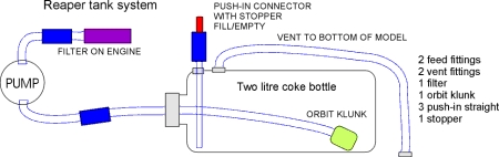
1. Reaper. [single tank]
A two litre Coke bottlle or a square white spirit bottle has one
feed fitting in the cap, one vent fitting in the side of the
bottle, and an Orbit klunk.
Another vent fitting is used in the bottom of the model for
overflow.
2. Javelin. [2 tanks into 1]
Two 1 litre apple juice bottles, each with feed and vent fittings
and felt klunks, are fed through a T fitting to the main tank.
This is a rigid 3/4 litre tank with vent connected to the T
fitting. The feed to the pump uses an Orbit klunk.
This tank is a reserve and is normally still full at landing.
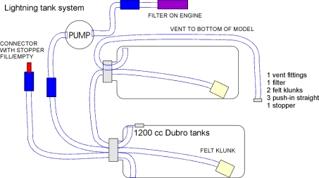
3. Lightning. [two tanks in line.]
A Dubro 1200cc tank with felt filter feeds to the vent of another
similar tank, which feeds the engine.
The Orbit is too big to fit in the Dubro tank.
3b. The Lightning and Hunter now have a single 3 litre tank with
orbit filter, as shown above.
Bigger size, lighter, cheaper, and easier to fit than the two
dubro tanks!
TIP. Mount the pump as low as
possible in the model.
It will prime more easily and will retain some fuel for a quick
start next time.
 |
||
 |
Duct design.
There is some disagreement about whether full ducting round the
engine is desirable. Some say that full ducting will produce more
thrust and higher performance. I think that full ducting has very
little or no influence on the static thrust, and its effect
in flight is difficult to assess. I have flown the same model
with and without, and noticed no difference. I fly scale jets,
and my intention is always to try to fly at scale speed. This
means throttling back after takeoff, to scale (slow) speed.
If full ducting does in fact help thrust at high speed, then it
would only benefit if you want to fly very fast.
To make a vertical climb in
aerobatics requires more power than level flight. A model with
very high static thrust
would be able to fly slowly and use extra power to climb to the
top of a loop, reducing to idle power in the descent,
always keeping to a scale speed. A model with low thrust has to
approach the loop at high speed to have enough
momentum to reach the top.
What is needed for a realistic scale model is high static thrust
for take-off and climbing, but no need for high speed capability.
The disadvantages of full ducting are obvious.
Cost.
Extra work to install.
Taking up precious space in the model and making the rest of the
installation, and later maintenance more difficult.
Extra weight.
Some people have used full ducting as a protection for the
turbine from loose items inside the model. But how about FO (
foreign objects) entering the intakes and being directed straight
to the turbine, causing FOD (foreign object damage)?
It seems to me that a simple metal gauze filter on the turbine
intake is a better option. (and it works).
Airflow
around the turbine is not needed to 'keep the engine cool'. The
high speed gas flow inside the engine determines
the case temperature.
The fuel is used to raise the temperature to produce thrust. A
high temperature is desirable.
Its the inside of the model which you want to keep cool.
Full ducting reduces the damage to the
fuselage from flames during hot starts. True, but it also make
hot starts invisible
and makes it much harder to deal with the fire. Without ducting,
and with manuel start, a hot start can usually be
dealt with in 2/3 seconds and a normal start begun immediately.
With full ducts and automatic start sequence,
a hot start can mean disaster (I've seen it happen).
One customer told me that his F15
gave very poor performance with full ducting. He now flies
without the engine
access cover, and thrust has improved 50%.
Rear exhaust ducting.
I have done some bench testing of rear ducting. My tests suggest;
1. All ducts reduce thrust. 1 to 2 Kg loss is
typical.
2. Duct sizes between 75mm and 95mm inlet
diameter gave similar results, so this is not critical.
3. Parallel or slight tapered ducts gave
similar results.
4. Air is drawn in to the duct with the jet
stream. Enough space must be allowed for this.
A gap between the engine efflux and the duct inlet is needed,
bigger gap for smaller pipe. About 20 mm gap is average.
5. Longer ducts loose more thrust.
6. Bifurcated ducts loose more thrust than
single pipes.
7. The higher the engine thrust, the greater
the thrust loss.
8. Any leak in the exhaust duct does not mean
hot gas escaping , but more air being drawn in.
NEWS. Well, I was
wrong. Work by John Wright has resulted in a lucky discovery.
The losses in the rear exhaust duct can be removed and a slight
INCREASE in static thrust can be obtained.!
Johns results have been published, and I intend to make all my
ducts to this concept in the future.
Of course you don't get this
improvement for nothing. The disadvantage is that there will be a
loss of thrust in flight at high speeds.
Important thing is- at what speed is the cross-over from thrust
increase to thrust loss? My guess is that it will be over 300 MPH
(480 kph)
so it wont bother most of us.
FAQ. "Will it fly off grass?". Yes, all our jets will fly off grass.
The relevant factors are - How long is the grass, is it wet grass,
is the ground smooth, how strong is the wind, are there
obstructions in the fight path,
how much thrust do you have.
We have flown the Assassin and Venom off grass, the latter with
only 10 lbs thrust.
Our flying field is tarmac so we dont get the chance to try grass
very often.
Many of our Super Reaper customers fly off grass with MW54
engines.
See HOME page for FAQ on foam wings,
servos, etc.
How does a model jet engine work?
The mechanics of typical model
turbo jet are very simple.
A compressor fan at the front is driven by a turbine wheel at the
back, both being mounted on a shaft with two bearings.
There are fixed vanes behind the front fan, and in front of the
rear turbine. The space around the shaft in the middle
is occupied by the combustion chamber, which is like a tin can
with many holes in it. Fuel is fed in from an electric pump
and on most designs, is evaporated inside hot metal tubes. There
is usually an outlet nozzle bolted on the back, and a
glowplug for ignition.
The compressor is a standard item from a car turbo charger. The
diffuser vanes behind this are machined into a light alloy plate
which is mounted in the outer case and supports the shaft
bearings. The turbine is like propellor with about 23 blades, and
is cast
in special Inconel material. It must stand very high forces at
high temperatures. The guide vanes in front of the turbine must
also
resist high temperatures, but as they are not spinning, the
forces are low. There are pipes to supply oil to the bearings,
and holes
feed air through the bearings to cool them. Most engines do not
need an oil tank system. The fuel is mixed with about 3% oil,
and this feeds the bearings from the fuel supply.
How do you start a model jet?
A can of gas is connected to the engine,
and the gas is ignited by a glowplug. The engine shaft is spun by
and electric starter motor.
As soon as the gas is alight, the fuel is fed in.(there is no
need to warm up the engine). The fuel ignites and the glow and
gas can be removed. The fuel feed is gradually increased as the
engine RPM increases, until the idle speed is reached, about 35,000
RPM.
The engine is now ready for flight.
The control of fuel feed in usually done by an electronic control
unit (ECU). This controls the fuel pump rate for starting and
acceleration to
full power at about 120,000RPM, and also provides several safety
cut-out systems.
So the start sequence is.
1 Turn on glow and gas.
2. Spin with the starter.
3. When ignition is heard, turn on the fuel.
4. Hold on the starter until idle speed is reached.
All the starting system can be carried on the model, and the ECU
controls the system to give self-starting from the Tx.
PROSKIN
Fitting the top wing skin.
With the wing held on the building board, the ribs must be sanded
using a straight sanding bar
so that they give a perfect level surface for the Pro-skin
covering. The ply leading edge should
be given a champher to match the rib profile. Take care with this
stage, the quality of the finished
wing will depend on it.
Cut a Proskin panel slightly over size, remove the protective
film from each side and lay in place
on the wing. Mark register points at each end of the spar to
align the skin at the glueing stage.
Now have a practice run at fitting the Pro-skin. Hold the skin
down with straight bars and weights
similar to the picture. Tapeing the edges down is not good enough.
There will be a rippling effect
between each piece of tape. A solid wood or metal bar can be
clamped in place as shown.
Check carefully that the skin lies flat without ripples.
When you are satisfied, the skin can be glued in place.
Apply a thin bead of Pro-bond urathane adhesive to all parts of
the wing, (or you can use slow
setting Cyano or epoxy)
Place the skin on to the alignment marks and fit the weights and
clamps as before.
You must work quickly to fit the skin within 5 minutes.
Rub down the skin over all joints to squeeze out excess adhesive,
and leave to dry for about 30 minutes.
If you make a mistake, it is possible to pull the skin off before
the glue is fully hard.
The Pro-bond dries from moisture in the air and in average
conditions, will be handleable in 20 minutes.
Full hardening will take 24 hours.
Trim off the skin edges.
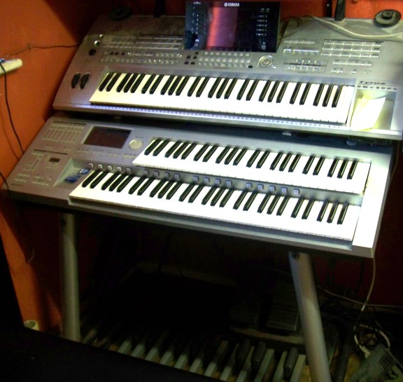 Yamaha D-Deck with Tyros above. |
The MIGHTY TYROS ORGAN! The
Tyros is fitted on wall brackets over the Yamaha D-Deck
organ. The tyros speakers have been replaced with Sony home
cinema To set up;- Function, Midi, Midi pedal 2, Edit,
Recieve. |
|